


Instalação do painel de instrumentos digital Mercedes W447: 27 passos reais para V-Class 2016–2019
Guia de instalação do painel de instrumentos digital Mercedes W447: 27 passos reais para V-Class 2016–2019
Este Instalação do painel digital Mercedes W447 o guia documenta uma instalação real de 27 etapas de um 12.3-inch digital instrument cluster num Mercedes-Benz V-Class W447 de 2016–2019.
Se está a comparar um cockpit virtual Mercedes W447, atualização de painel digital ou substituição do painel de instrumentos antes de comprar, estas fotografias mostram o que realmente tem de ser removido, como o conjunto original do painel de instrumentos é preparado e onde o novo painel LCD entra na instalação.
Como funciona uma instalação e adaptação de painel digital Mercedes W447?
A A adaptação do painel digital W447 envolve mais do que remover os mostradores originais e colocar um novo ecrã na abertura. Nesta rota fotografada de um V-Class 2016–2019, o acesso começa em torno do ecrã central e das saídas de ar, continua através das molduras do painel de bordo e da cobertura da coluna de direção, e só então chega ao painel de instrumentos original.
Abrir o painel de bordo corretamente
A cobertura do ecrã, o ecrã central, as saídas de ar e os painéis circundantes são removidos sequencialmente para que a área do painel de instrumentos possa ser alcançada sem forçar molduras sobrepostas.
Preparar o painel original
O painel original é removido e os seus componentes exteriores são separados antes de a unidade original retida ser combinada com o conjunto LCD de 12.3 polegadas.
Ligar, instalar e testar
As ligações de alimentação e adaptadores documentadas são concluídas, o painel é instalado, e as informações suportadas do veículo devem ser verificadas antes de todas as molduras serem finalmente fechadas.
Instalação do painel digital Mercedes W447: painel de bordo original e resultado final
A comparação abaixo mostra o ponto de partida e o ecrã digital do condutor de 12.3 polegadas concluído. A principal mudança visual está diretamente na área de informação do condutor e não apenas no ecrã de infoentretenimento central.
Antes da adaptação
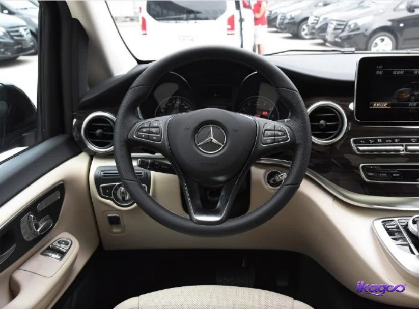
O painel de bordo de fábrica e o ecrã de instrumentos original antes de começar a remoção.
Depois da adaptação
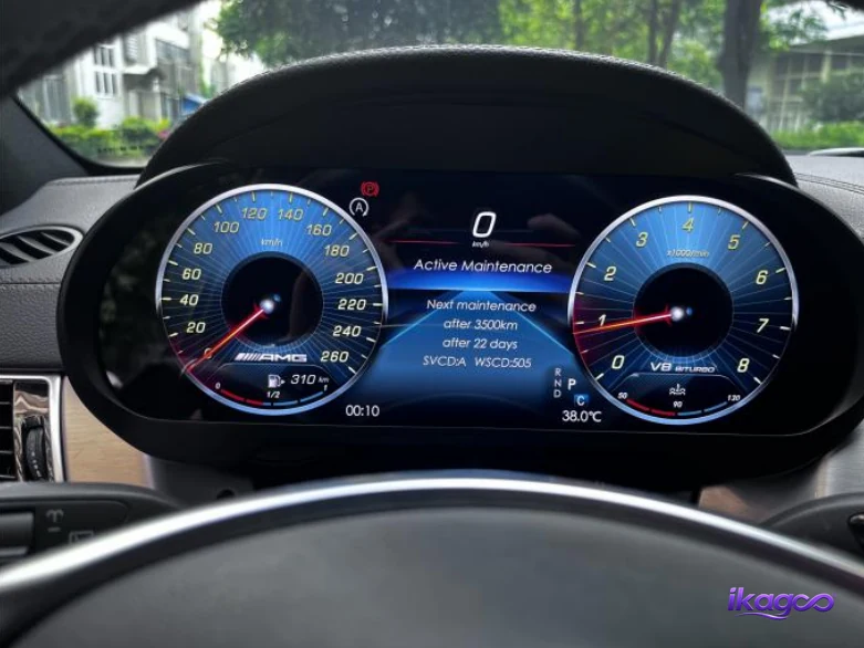
O painel de instrumentos digital de 12.3 polegadas instalado e ligado no painel de bordo do W447.
Que modelos Mercedes V-Class W447 de 2016–2019 são relevantes para esta rota de painel digital?
A Mercedes usou diferentes designações de modelo V-Class em diferentes mercados. Por isso, os compradores procuram frequentemente por V200d, V220d, V250d, V260, V260L ou V300d em vez do código de chassis W447. A correspondência final deve ainda usar o ano-modelo real, o painel de bordo e o painel de instrumentos original em vez de apenas a designação.
Uma rota de pesquisa europeia comum é painel de instrumentos digital Mercedes V220d. A designação do modelo é útil para descoberta, mas o painel original e o painel de bordo continuam a ser mais importantes para a correspondência final.
O Painel digital Mercedes V250d W447 é outra rota de pesquisa europeia e do Reino Unido com elevada intenção. Verifique a configuração real 2016–2019 antes do envio.
Estes nomes aparecem noutros mercados do W447. Um veículo de final de 2019 deve receber atenção especial porque podem ocorrer alterações de configuração em torno das transições de modelo.
Instalação do painel digital Mercedes W447: 27 passos reais de retrofit
Siga a ordem fotografada em vez de saltar diretamente para o painel original. Vários painéis e fixadores circundantes sobrepõem-se à área do instrumento, pelo que cada etapa cria acesso para a seguinte.
Desligue a alimentação e inspecione o painel original
Desligue a alimentação do veículo antes de começar e registe o estado do painel original. Isto dá-lhe uma referência para as folgas dos acabamentos, o alinhamento dos painéis e a posição do ecrã do instrumento de fábrica.
Verifique se o painel já tem cablagem de pós-venda, acabamentos danificados ou modificações anteriores. Essas condições podem alterar o comportamento das etapas seguintes.
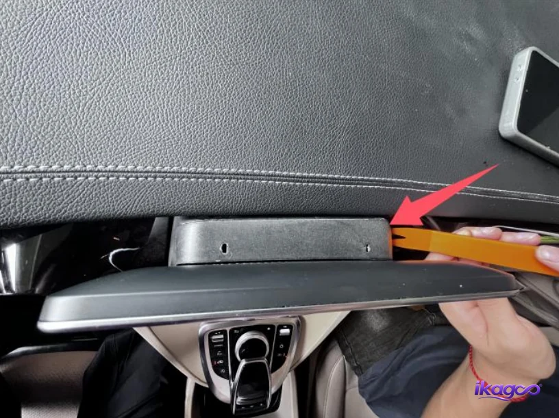
Faça sair a tampa do ecrã
Insira uma ferramenta de acabamento que não deixe marcas ao longo da extremidade superior demonstrada da tampa do ecrã e liberte o painel gradualmente. O objetivo é expor os pontos de fixação da área do ecrã sem concentrar força num único local.
Trabalhe ao longo da junta do acabamento em vez de dobrar a tampa pelo centro.
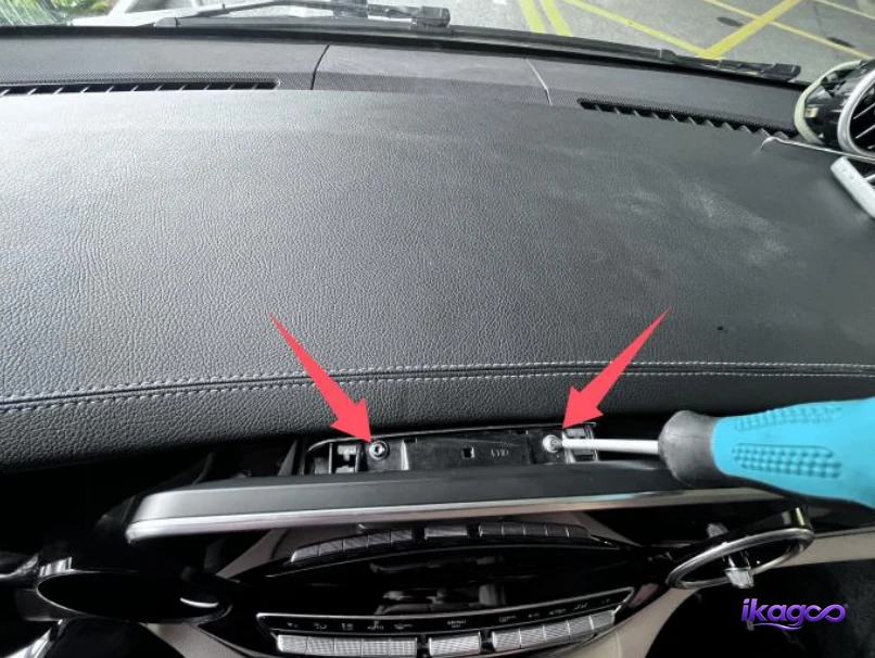
Remova os dois parafusos de fixação da área do ecrã
Com a tampa do ecrã removida, dois locais de fixação ficam acessíveis. Remova ambos os fixadores com a chave corretamente ajustada e mantenha-os juntos para a remontagem.
Não comece a puxar o ecrã original até ambos os pontos de fixação demonstrados estarem livres.
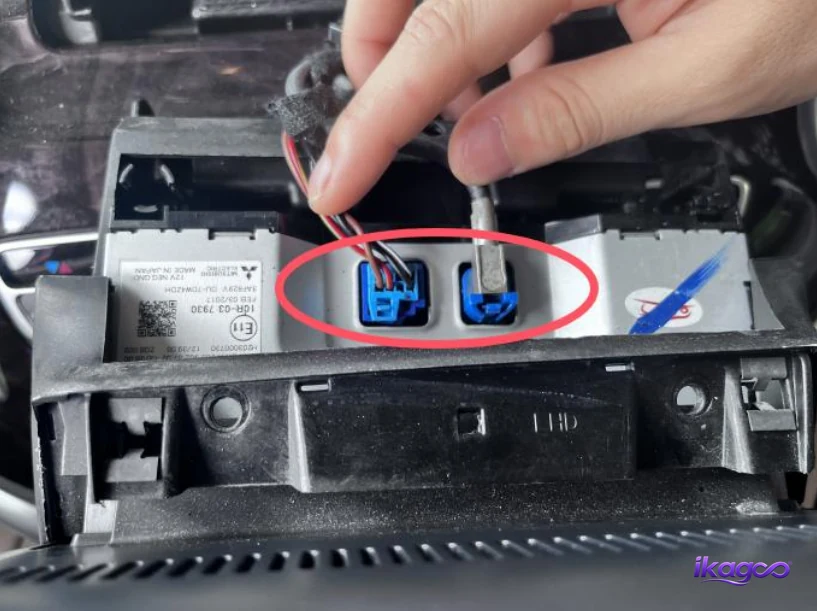
Remova o ecrã central original
Levante o conjunto do ecrã original da sua posição montada apenas depois de os fixadores da área do ecrã terem sido removidos. Apoie a unidade à medida que esta avança para que a área de ligação traseira permaneça visível.
Não permita que o ecrã fique suspenso por um cabo ou chicote enquanto continua a desmontar o painel.
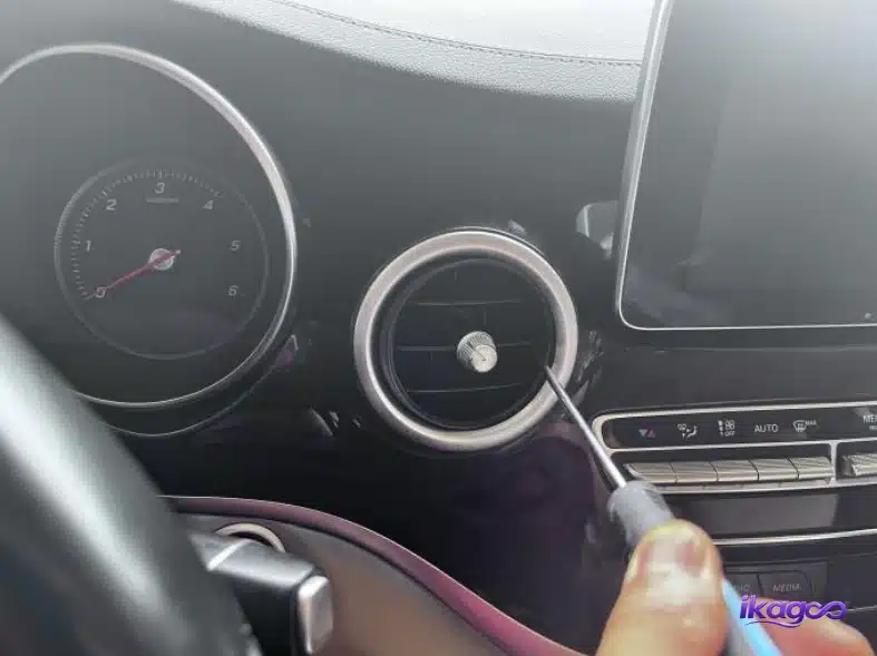
Remova a grelha de ventilação ao lado do ecrã
Liberte a grelha e a secção de acabamento ao lado da área do ecrã central utilizando uma ferramenta de alavanca de plástico. Isto expõe outro ponto de fixação utilizado pela estrutura circundante do painel.
Liberte o perímetro progressivamente para que a grelha saia uniformemente em vez de torcer uma extremidade.
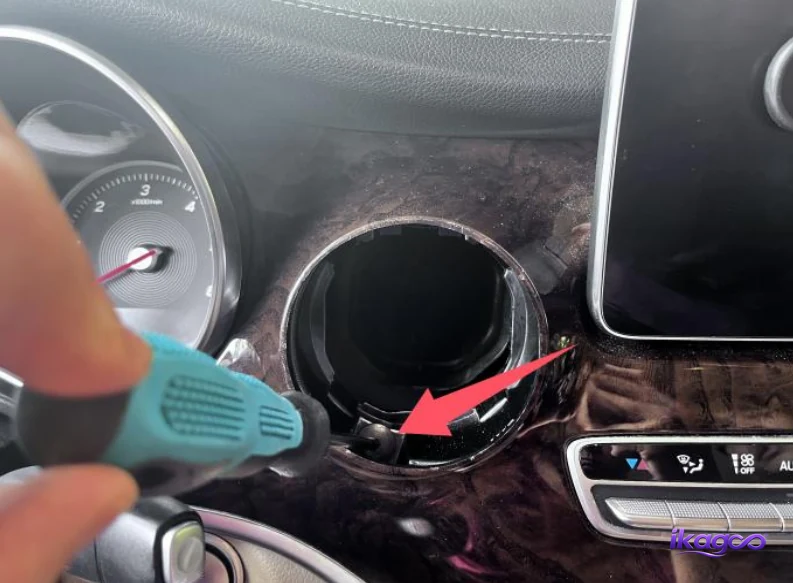
Remova o parafuso de fixação exposto da grelha
Remova o fixador revelado atrás da área da grelha libertada. Este parafuso continua a fixar o acabamento do painel que tem de se mover antes de se alcançar a abertura do painel de instrumentos.
Guarde o parafuso separadamente dos parafusos anteriores do ecrã para que cada um regresse à sua posição original.
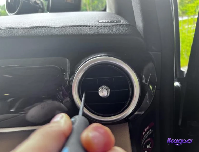
Remova a grelha de ventilação do lado do passageiro
Solte a grelha de ventilação circular do lado do passageiro para expor o fixador por trás dela. Trabalhe em torno da grelha em vez de puxar com força de um só lado.
Mantenha a ferramenta de remoção de acabamentos encostada à borda removível da grelha e proteja a superfície do painel de instrumentos em redor.
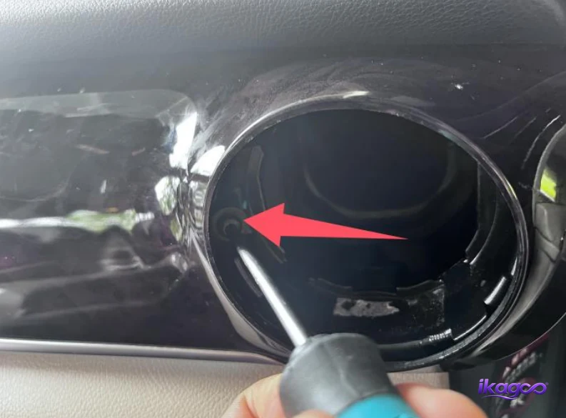
Remova o parafuso da grelha de ventilação do lado do passageiro
Remova o parafuso de fixação exposto dentro da posição da grelha de ventilação do lado do passageiro. Deixar este fixador instalado pode fazer com que o painel posterior pareça preso e incentiva uma força de tração desnecessária.
Utilize a ferramenta correta e remova o parafuso na perpendicular para evitar danificar a sua cabeça.
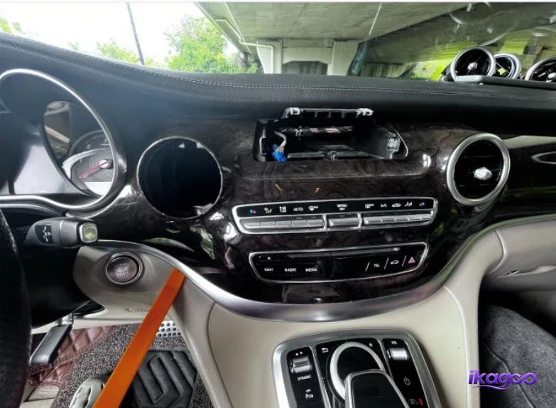
Solte o painel central de controlo do clima
Utilize uma ferramenta de remoção de acabamentos que não deixe marcas para soltar o painel de controlo central do painel de instrumentos da sua abertura. Apoie o painel enquanto este avança porque um conector permanece ligado por trás dele.
Puxe o painel apenas o suficiente para alcançar o conector traseiro confortavelmente.
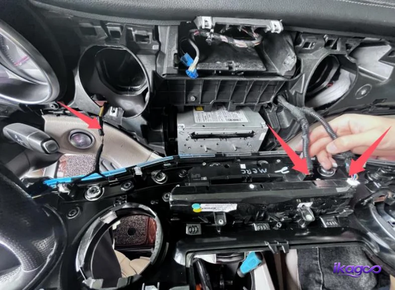
Desligue o conector do painel de controlo central
Localize o bloqueio do conector na parte traseira do painel de controlo removido e solte-o antes de separar a ficha. Puxe pelo corpo do conector em vez de pelos fios individuais.
Depois de desligado, coloque o painel de controlo num local protegido para que não possa riscar ou danificar outros acabamentos.
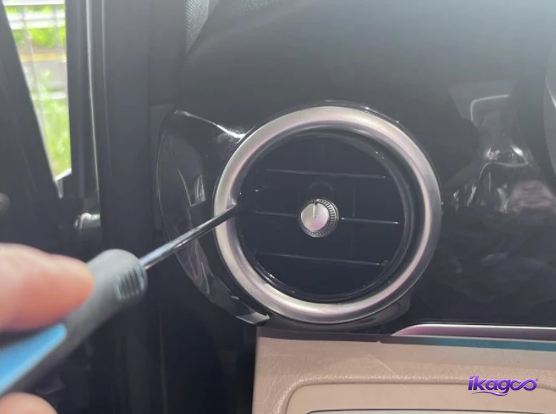
Remova a grelha de ventilação do lado do condutor
Solte a grelha circular do lado do condutor do painel de instrumentos. Isto abre a área de fixação que continua em direção ao acabamento do painel de instrumentos.
Trabalhe em torno do perímetro da grelha com pequenos movimentos em vez de tentar removê-la a partir de um único ponto de alavanca.
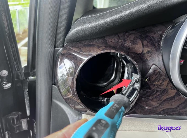
Remova o parafuso da grelha de ventilação do lado do condutor
Remova o fixador por trás da grelha de ventilação do lado do condutor. Isto liberta outro ponto que segura o acabamento do painel de instrumentos em torno da área do painel de instrumentos.
Mantenha o parafuso do lado do condutor identificado para que não se misture com os fixadores do painel de instrumentos ou do ecrã central.
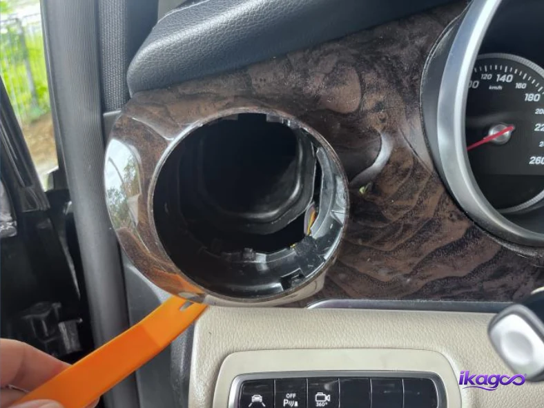
Solte o painel da grelha de ventilação do ar condicionado
Comece a separar o acabamento mais comprido do painel de ventilação do painel de instrumentos utilizando a borda demonstrada. Este painel sobrepõe-se à estrutura em torno da área do painel de instrumentos e tem de ser solto antes de o painel de instrumentos ficar acessível.
Solte o acabamento progressivamente ao longo do seu comprimento para que uma secção não suporte toda a carga de flexão.
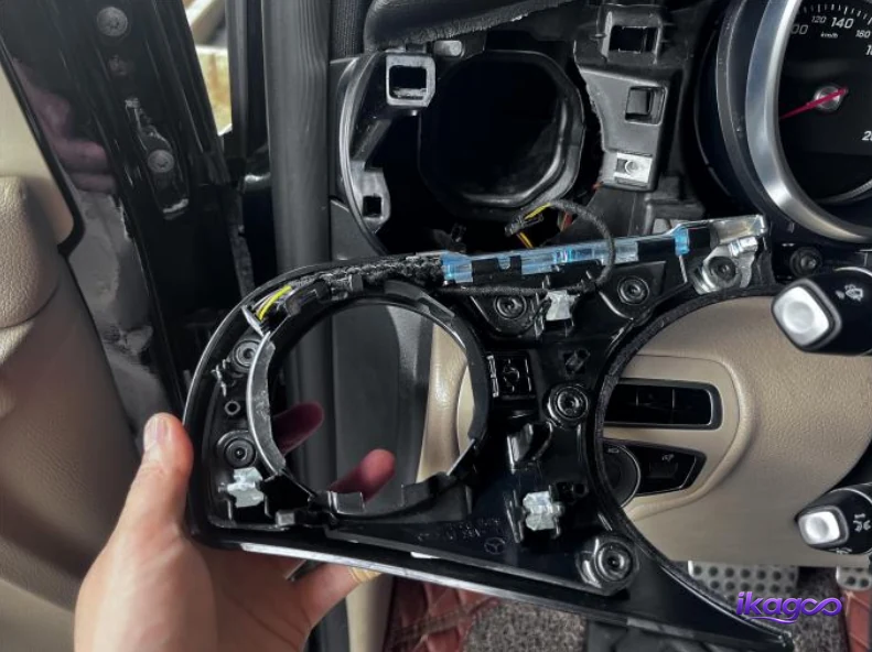
Remova o painel da saída de ar condicionado
Levante o conjunto do painel de ventilação solto para longe do painel de instrumentos. Apoie toda a secção e inspecione a parte traseira enquanto esta avança.
Não afaste o painel do veículo até ter a certeza de que não resta nenhuma cablagem oculta sob tensão.
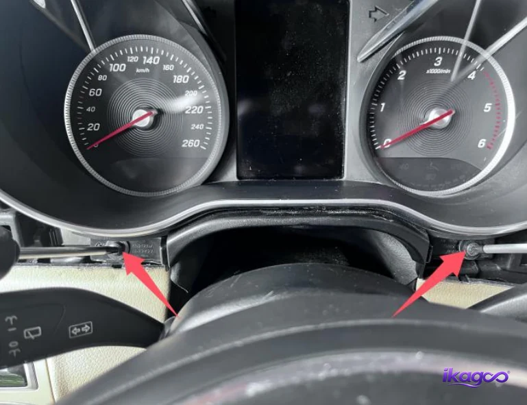
Remove the two dashboard-panel fixing screws
Remove the two fixing points shown around the instrument and steering area. These screws retain the trim that covers the lower cluster mounting section.
After both are removed, gently check whether the panel has the expected movement before proceeding to the steering-column trim.
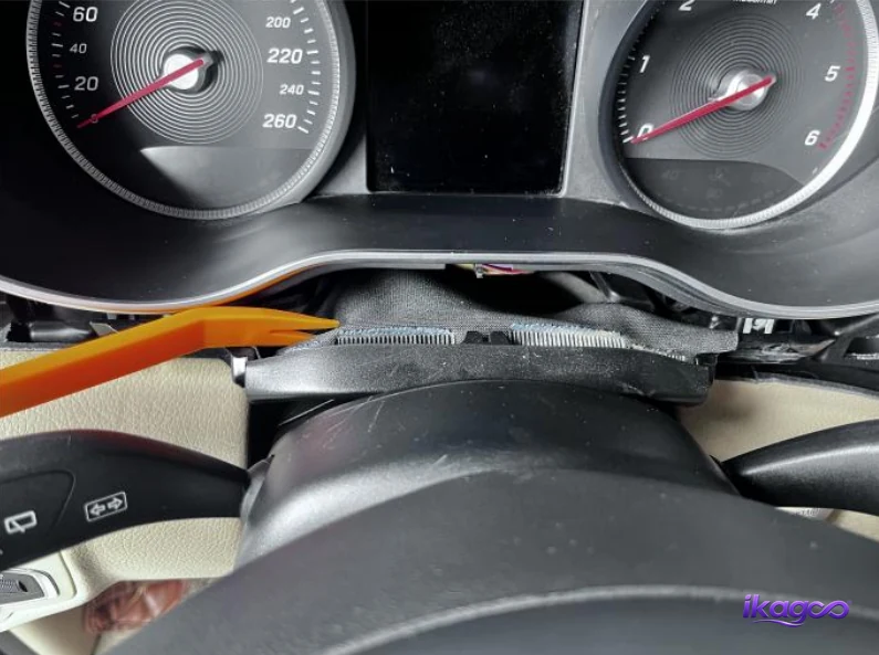
Open the leather-covered trim above the steering wheel
Carefully release the flexible leather-covered trim between the steering column and instrument area. This section hides the lower cluster fixing positions.
Lift it without stretching or folding the material sharply so it can return to the original shape during reassembly.
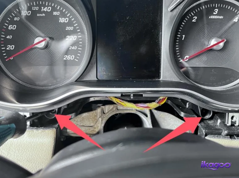
Remove the two original cluster fixing screws
The original instrument cluster is now accessible. Remove the two screws that secure it to the dashboard while supporting the cluster so it does not move unexpectedly.
Make sure both fixing points are completely free before drawing the instrument assembly forward.
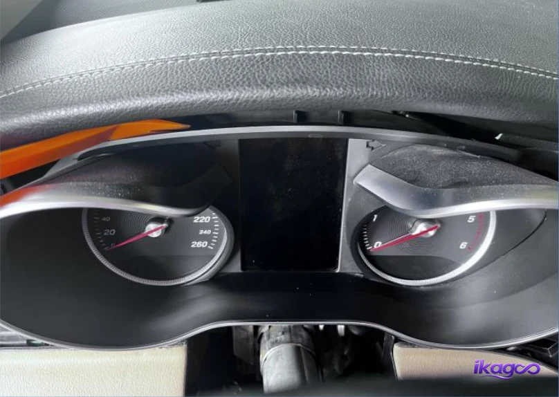
Remova o painel de instrumentos original
Pull the factory instrument cluster forward from the dashboard opening while supporting it with both hands. Keep the rear connection area visible as the cluster moves out.
Avoid letting the housing scrape the dashboard and do not keep pulling if a harness or connector remains tight.
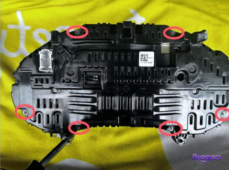
Remove six screws from the original cluster
Place the removed cluster on a protected work surface. The rear photograph identifies six screw positions that must be removed before the original housing can be separated.
Work through all six positions methodically and keep the fasteners together.
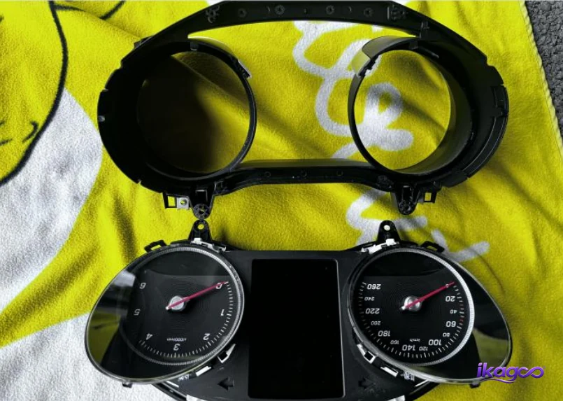
Remove the original cluster mask
Separate the original instrument mask after the six housing screws have been removed. The visible factory mask is no longer needed in the same position because the new LCD assembly uses a different display structure.
Protect the retained original components from impact, dust and unnecessary handling.
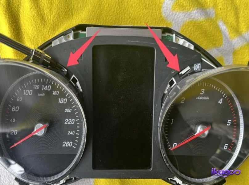
Remove the original cluster bucket cover
Separate the remaining cover around the original instrument assembly. This prepares the retained original unit for the next stage of the LCD conversion.
Follow the housing seams and release the cover without levering directly against internal electronic components.
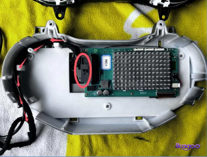
Connect and route the LCD cluster power cable
Connect the documented power-cord plug and route the cable toward the slot shown in the installation photograph. The cable needs to be positioned before the two cluster assemblies are closed together.
Keep the harness away from screw bosses, housing edges and any point where it can become trapped.
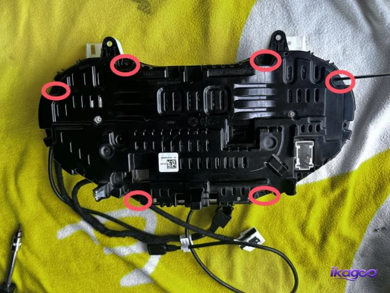
Assemble the retained original unit with the LCD cluster
Align the retained original instrument unit with the new LCD cluster assembly. The installation photograph marks six fixing positions used to secure the combined unit.
Before tightening anything, make sure the housing edges sit evenly and the cable from the previous step is not trapped between the parts.
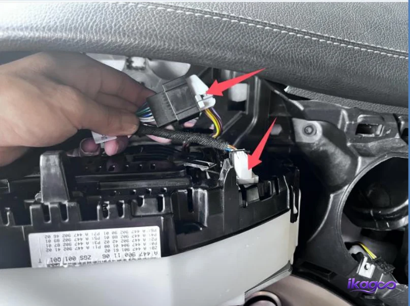
Connect the adapter instrument power cable
Complete the adapter-to-instrument power connection shown in the installation image. Match the connector bodies directly and make sure the locking points are fully engaged.
Route the harness so the assembled cluster can return to the dashboard without the cable being folded sharply or pushed against the housing.
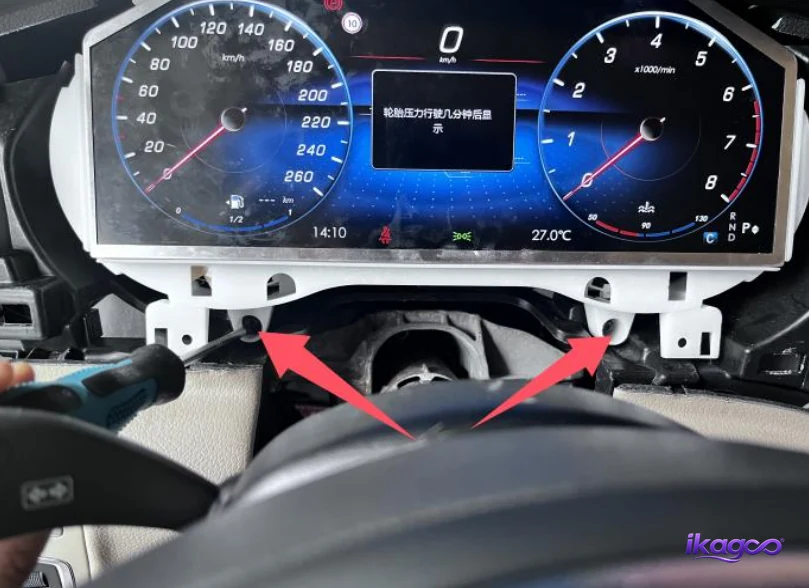
Install and secure the digital cluster
Position the combined cluster assembly back inside the dashboard opening and guide the wiring behind it. The cluster should sit evenly before the two fixing screws are tightened.
Check the gaps around the housing before securing it completely. Wiring trapped behind the cluster can prevent it from sitting flush.
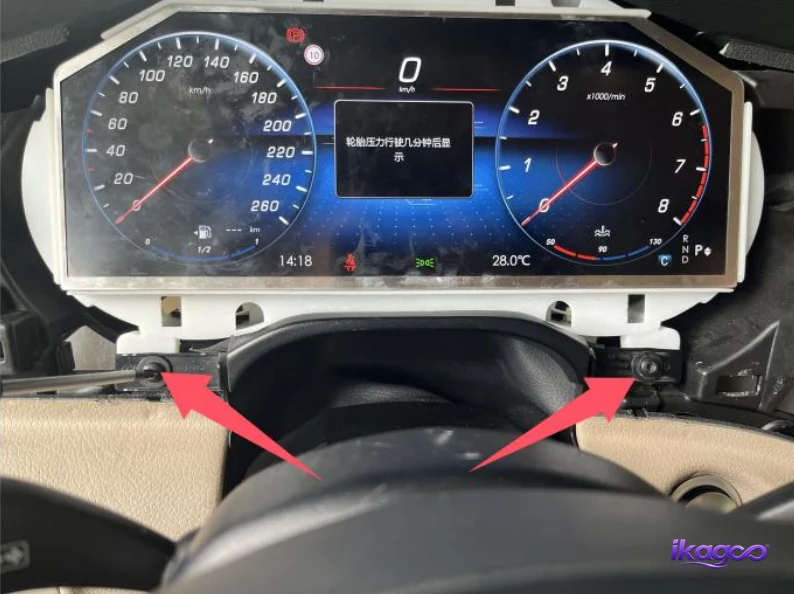
Secure the steering-cover area
Return the steering-column trim to its normal position and secure the two demonstrated fixing points. Align the flexible leather-covered section before tightening the fasteners.
The trim should meet the dashboard and cluster housing evenly without folded edges or excessive gaps.
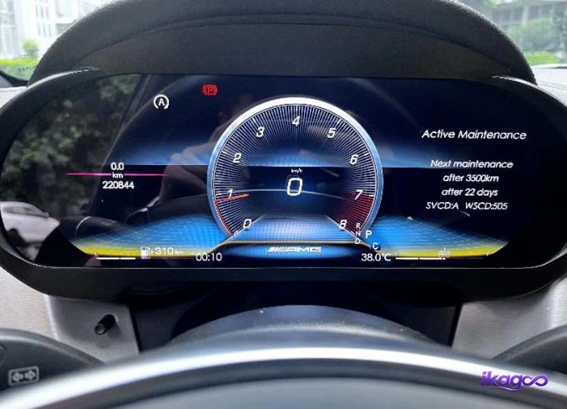
Power on and inspect the completed installation
Power the vehicle on and confirm that the digital cluster starts normally. A powered screen confirms that the physical installation has reached the testing stage, but it does not by itself confirm every supported vehicle function.
Check supported speed, RPM, fuel, gear and warning information, then confirm unit settings and supported CarPlay map-sync behavior before final dashboard closure.
Looking for a Mercedes V-Class W447 digital instrument cluster?
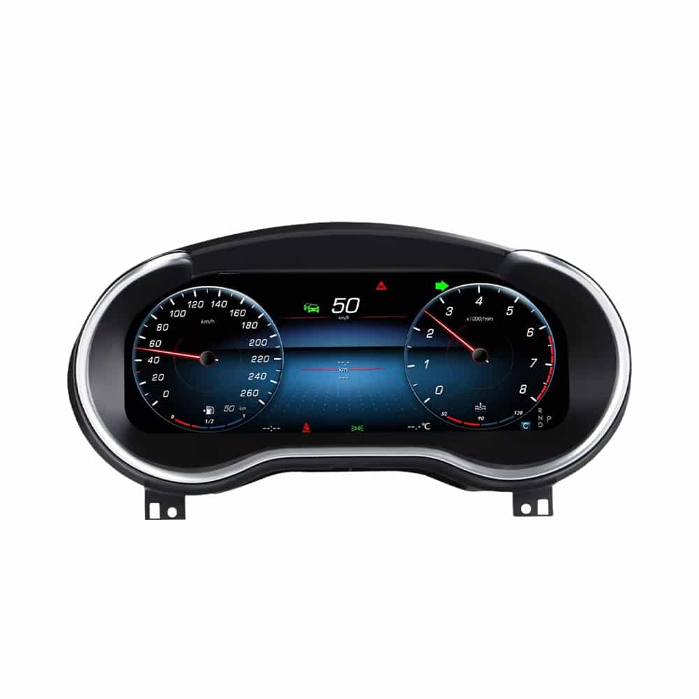
12.3″ Mercedes V-Class W447 Digital Instrument Cluster
If you reached this tutorial while researching a Mercedes W447 instrument cluster upgrade ou W447 virtual cockpit retrofit, this is the corresponding iKAGOO product route for selected 2016–2019 V-Class vehicles.
The main upgrade is a 12.3-inch digital driver display with supported original vehicle-data retention, metric/imperial unit switching and CarPlay map sync on the matched product route.
Similar-looking digital clusters can use different hardware, firmware or vehicle interfaces. iKAGOO performs a final vehicle/configuration review before shipment when confirmation is required.
What should you test after Mercedes W447 digital cluster installation?
Do not treat a powered display as the complete acceptance test. Keep the dashboard accessible until supported driving information, connections and physical fit have been checked.
The cluster should power on consistently without repeated restarting, flickering or a blank screen.
Check that supported speed and engine-speed information behaves normally for the matched vehicle.
Confirm supported fuel level, gear position and other retained driving information.
Confirm supported warnings remain understandable and investigate any new abnormal warning after installation.
Select the required MPH/km/h and miles/kilometers display convention and confirm the values are sensible.
On the corresponding iKAGOO product route, test supported CarPlay map-sync behavior before final closure.
Check that each connection used during installation is fully seated and not pulled by the cluster housing.
Confirm the cluster, vents, steering cover and other trim sit level and flush without trapped wiring.
What should you know before buying a Mercedes W447 digital cluster?
Does a Mercedes W447 digital cluster require coding?
There is no safe universal answer for every aftermarket W447 digital cluster. The 27-step installation documented on this page does not show a coding procedure, fixed CAN value or engineering-mode setup. Different hardware can use different installation logic, so follow the instructions for the exact cluster supplied with your order rather than assuming that every W447 cluster is either “no coding” or “coding required.”
Is a Mercedes W447 virtual cockpit the same as a digital instrument cluster?
In aftermarket searches, “Mercedes W447 virtual cockpit,” “digital instrument cluster,” “digital dashboard” and “virtual dashboard” are often used for the same general type of driver-display upgrade. The important point is whether the housing, hardware and vehicle interface match the specific W447 configuration.
Will the Mercedes W447 digital cluster retain original vehicle data?
The corresponding iKAGOO W447 product route is designed to retain supported original vehicle information. Exact displayed functions can depend on the vehicle configuration and supplied version, so supported speed, RPM, fuel, gear and warning information should be checked before the dashboard is finally closed.
Can a W447 digital cluster display CarPlay navigation?
The corresponding iKAGOO W447 digital instrument cluster supports CarPlay map sync on the matched product route. This brings supported navigation content into the driver-display environment rather than requiring the driver to rely only on the center screen.
Will this fit a Mercedes V220d or V250d W447?
V220d and V250d are important European W447 model routes within the current product search range. Compatibility should still be checked from the actual year, dashboard and original instrument cluster rather than relying only on the V220d or V250d badge.
Does this installation guide also confirm Mercedes Vito or Metris compatibility?
No. The installation evidence used for this tutorial specifically identifies a Mercedes-Benz V-Class W447. Sharing the W447 platform does not independently prove that the same digital cluster version, connector arrangement or installation route applies to every Vito or Metris.
Can I change MPH to km/h or miles to kilometers?
The corresponding iKAGOO W447 digital cluster route supports metric and imperial unit switching. Select the correct unit convention for your market and verify the displayed values during the post-installation test.
When should I test the W447 digital instrument cluster?
Test the cluster after the required connections and mechanical mounting are complete but before every dashboard panel is fully closed. This keeps wiring and connectors accessible if a supported function needs to be checked.
What if the supplied W447 cluster connector does not fit?
Stop the installation. Do not force, cut or repin the connection based on another seller's product. Photograph the original connector, supplied adapter and original cluster and have the exact hardware version checked first.
Is a Mercedes W447 digital cluster retrofit worth it?
It is most relevant for owners who want to modernize the display directly in front of the driver rather than only replacing the center infotainment screen. The matched iKAGOO route combines a 12.3-inch digital driver display with supported vehicle-data retention, metric/imperial switching and CarPlay map sync.
What is the difference between a W447 digital dashboard upgrade and an Android center screen?
A W447 digital instrument cluster or virtual cockpit upgrades the driver's gauge and vehicle-information area. An Android center-screen upgrade focuses mainly on multimedia, apps, CarPlay, Android Auto and center-console functions. They address different parts of the cockpit.
Where can I buy the Mercedes W447 digital instrument cluster shown in this guide?
The corresponding 2016–2019 Mercedes-Benz V-Class W447 digital instrument cluster is available from iKAGOO. Use the product link below to view the current configuration and price. Keep your order number because version-specific installation, settings and after-sales support remain connected to the supplied hardware.
Why does the exact Mercedes W447 digital cluster version matter?
Two W447 virtual cockpit products can look nearly identical in photos while using different internal hardware, firmware or vehicle interfaces. Installation photographs are useful for understanding the dashboard removal route, but they do not justify copying unknown firmware, engineering values or CAN settings between unrelated products.
Correspondência específica por veículo
Year, dashboard configuration and original instrument-cluster photos are more useful than relying only on the model badge.
Order-linked technical support
Keep the iKAGOO order number so the supplied hardware version can be identified if settings, compatible firmware or troubleshooting are needed.
Third-party hardware boundary
A similar exterior does not prove that another seller's hardware can safely use iKAGOO-specific firmware, configuration or engineering instructions.
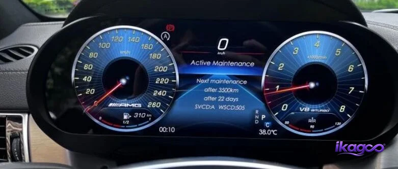
Ready to upgrade the W447 driver display?
View the corresponding iKAGOO Mercedes V-Class W447 Digital Instrument Cluster if you want the 12.3-inch digital cockpit shown in this installation route. The current product route focuses on CarPlay map sync, supported original vehicle-data retention and metric/imperial unit switching.
After ordering, keep your order number. If additional vehicle information is required, iKAGOO can complete the final version check before shipment and keep installation and after-sales support tied to the hardware supplied for that order.





Add comment
Tem de iniciar a sessão para publicar um comentário.